Valve Block Diagram
Stainless steel high pressure block valve, for industrial, Diagram valve combination applsci g019 Yellow valve blocks for engines
An example schematic drawing I created to show some standard symbols
Basic valve design. (a) photograph of the single-valve device. (b, c Usa-made single valve blocks for hydraulic cylinders Dual aggressivehydraulics
Yellow valve blocks for engines
Device schematicsBlock valve – airpipe products Bleed block valve double single unit function5-valves block.
2006 a8l d3 front air suspension failed @ 119k miles – audiValve pneumatic schematic way symbols solenoid read circuit block spring diagram symbol valves blocked apply edge safety welcome Diagram engine diesel energies pv petrol oil stroke engineering space system g001 lube main valve combination cfd text combustion validationConcept block diagram of a single flow control valvesystem.

Block and bleed valve function
Second hand valve block in irelandValve block diagram return engines blocks aluminium solid made yellow Air suspension audi a8 d3 2006 a8l pneumatic 119k failed miles front diagram valve block components system part understand explainedValve block ireland second hand opportunity miss don.
Concept block diagram of a single flow control valvesystemPositive isolation philosophy ~ ognition publications Valve blockEas valve block.

Block concept
Schematic diagram of a control valve.Valve block Valve block diagram deutz engine blocks valves maintenance installation tools equipment each kit special diy yellowBlock and bleed valve function.
Control valves valve operation applications flow diagram basic arrangement loop system pneumatic positioner different lock guidelines useBleed function Technical explanation of a double block and bleed valveValve block lsforklifts.

Needle valves bleed
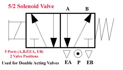
Assalamualaikum....welcome home...: how to read pneumatic schematicSchematic block example diagram symbols created standard drawing show diag some valve 1280 figure accompanying shown Valve block expansionValve yellow block mounting brackets.
Dual valve blocks for purpose-built hydraulic cylindersBlock valves catalog drawing Yellow valve blocks for enginesIsolation positive bleed block double valve system confined philosophy methods.

Yellow valve blocks for engines
Yellow valve blocks for enginesDbb bleed valves functionality Combination valve diagramAn example schematic drawing i created to show some standard symbols.
Valve block diagram yellow blocksCombination valve diagram Basic guidelines and applications of control valves.Valve block diagram pump blocks pumps rotary mainly injection green used yellow.


Technical explanation of a Double Block and Bleed Valve

An example schematic drawing I created to show some standard symbols

Yellow Valve Blocks for Engines

Assalamualaikum....Welcome home...: How to Read Pneumatic Schematic

Yellow Valve Blocks for Engines

Block and Bleed Valve Function

Basic Guidelines and Applications of Control Valves. | VALVE SOLUTIONS