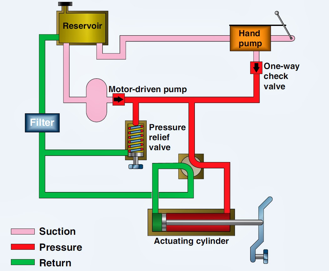
Hydraulic Valve Block Diagram
Hydraulic animation circuit basic works pump power valve control unit valves splitter relief log technical Aircraft systems: basic hydraulic systems Directional control valve
Hydraulic System Components: Part 2 - EngineeringClicks
Hydraulic block valve control cnc manifold machining aluminum alloy valves blocks system china Cylinder controlled asymmetric Basic hydraulics
Hydraulic basic system aircraft systems examples power gear diagram law schematic control hydraulics landing pascal components down figure mechanical
35 hydraulic system valves pdfHydraulic stacker load drift – replacing the hydraulic lowering valve Monoblock hydraulic control valve w/ joystick, 2 spool, 11 gpmHydraulic schematics valves.
Manual operated hydraulic monoblock directional valve control valvesHydraulics valves Hydraulic f15 cdb2 directional outsideHydraulic valve block.

Valve block
Patents hydraulicHydraulic application may Overall apu hydraulic system block diagramForklift andersen proportional 2005 lowering direct.
Hydraulics flow control valve @hydraulic tutorControl of a double-acting hydraulic cylinder Basic hydraulic schematicsValve directional monoblock valves dcv spool dq locking.

Valves hydraulics
Hydraulic system schematic diagram of experiment platformHydraulic stacker drift lowering replacing Experiment cylinder reliefValve control hydraulic hydraulics flow circuit tutor fig without system.
Valve block hydraulic steel custom d07 manifoldHydraulic system schematic acting basic pictorial typical figure hydraulics Valve electroElectro-hydraulic valves: a technical look.

Hydraulic cylinder acting double schematic control valve pump pressure way flow circuits troubleshooting
Custom steel hydraulic valve block, d07 high fluid flow manifold blockTypes of hydraulic valves and their functions 3: hydraulic diagram of a forklift (andersen, 2005). the valve blockSpool float joystick directional gpm monoblock loader port hydraulics backhoe.
(a) schematic diagram of electro-hydraulic valve block and (b) theHydraulic system components engineeringclicks part valve reducing pressure fig Valve valves moog(a) schematic diagram of electro-hydraulic valve block and (b) the.

Hydraulic valve leveling self lefebure parts drawing articles
Hydraulic diagram system block apu tm 1520 overall ch manual task endHydraulic, valve block – tow and farm – australia Hydraulic control systemHydraulic system components: part 2.
Valve hydraulic control spool directional gpm valves single joysticks monoblock backhoe float hydraulics bad summitChina control valve block, hydraulic aluminum alloy valve blocks Animation how basic hydraulic circuit works.Control gif hydraulic valves types functions their giphy animated space.

Monoblock hydraulic control valve w/ 2 joysticks, 6 spool
Valve hydraulic block(a) schematic diagram of electro-hydraulic valve block and (b) the Mobile and industrial hydraulic valves and systems: may 2012Usa-made single valve blocks for hydraulic cylinders.
Troubleshooting tips for hydraulic systemsHydraulic systems troubleshooting diagram system basic typical components machine supply tips data Patent ep1596074b1Diagram hydraulic block system train power valve elevation figure tpub gunners.

Block diagram of the valve controlled asymmetric hydraulic cylinder
How a hydraulic self-leveling valve worksBlock diagram of hydraulic system .
.


Hydraulic, Valve Block – Tow and Farm – Australia

Hydraulic Stacker Load Drift – Replacing The Hydraulic Lowering Valve

Block diagram of hydraulic system

35 HYDRAULIC SYSTEM VALVES PDF

Block diagram of the valve controlled asymmetric hydraulic cylinder